##### Testing, debugging and restart
| Mouse wheel | change slice |
| Ctrl + Mouse wheel | zoom |
| Right mouse button (hold down) | pan |
| Left mouse buttom click | change position of crosshair (world position) |
| Middle mouse button | Change windowing |
| Ctrl + Left Mouse button hold | Reformatting MPR (rotation/translation) , see Navigation Tool |
| 1-6,0 | shortcuts to standard CT windowings |
| Space | toggle ROI edit, see[ ROI tool](https://www.nora-imaging.org/doc/books/nora-documentation/page/roi-tool "ROI-Tool") |
| s | open settings window |
| x,y | decrease/increase scroll speed |
| arrow up/down | change subject (when using autoloader) |
| (shift) Ctrl-Z | Undo/Redo ROI drawing |
| [](https://www.nora-imaging.org/doc/uploads/images/gallery/2020-09/image-1600356837328.png) | focuses the position of the viewer to the center of gravity of the current ROI |
| [](https://www.nora-imaging.org/doc/uploads/images/gallery/2020-09/image-1600356743419.png) | turns the ROI to be the "current ROI" on which currently is drawn on |
| [](https://www.nora-imaging.org/doc/uploads/images/gallery/2020-09/image-1600356769770.png) | toggles the visiblity of the ROI in all viewports |
| [](https://www.nora-imaging.org/doc/uploads/images/gallery/2020-09/image-1600356803683.png) | open several options to modfiy ROIs (see below: ROI operations) |
| [](https://www.nora-imaging.org/doc/uploads/images/gallery/2020-09/image-1600356868723.png) | save the ROI (upload to server) |
| [](https://www.nora-imaging.org/doc/uploads/images/gallery/2020-09/image-1600356897331.png) | downloads the ROI to your local computer |
| [](https://www.nora-imaging.org/doc/uploads/images/gallery/2020-09/image-1600356924459.png) | erases/clears all on voxels of the ROI |
| [](https://www.nora-imaging.org/doc/uploads/images/gallery/2020-09/image-1600356948798.png) | deletes the ROI from workspace |
| [](https://www.nora-imaging.org/doc/uploads/images/gallery/2020-09/image-1600428072743.png) | ##### **Thresholding based pen**. Depending on the threshold (either choose clImL/R or an actual number) the pen turns voxels ON, which are above ("Higher") or below ("Lower") the threshold. Additional you can select "Higher RGrow"/"Lower RGrow" to enforce the ON voxels to be connected to the central voxel. [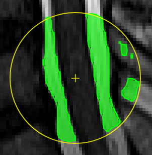](https://www.nora-imaging.org/doc/uploads/images/gallery/2020-09/image-1600432433860.png) |
| [](https://www.nora-imaging.org/doc/uploads/images/gallery/2020-09/image-1600428113719.png) | ##### **Magic pen (unconnected)**. Turns voxel ON, which have a 1) similar contrast compared to the central voxel, 2) are within pen's radius. The similarity depends on the color limits chosen for the current contrasts. [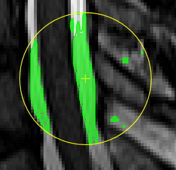](https://www.nora-imaging.org/doc/uploads/images/gallery/2020-09/image-1600432118373.png) |
| [](https://www.nora-imaging.org/doc/uploads/images/gallery/2020-09/image-1600428149703.png) | ##### **Magic pen (connected)**. Turns voxel ON, which have a 1) similar contrast compared to the central voxel, 2) are within pen's radius. and 3) are connected to central voxel via a **region growing approach.** The similarity depends on the color limits chosen for the current contrasts. [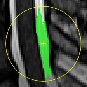](https://www.nora-imaging.org/doc/uploads/images/gallery/2020-09/image-1600432170357.png) |
| [](https://www.nora-imaging.org/doc/uploads/images/gallery/2020-09/image-1600428181303.png) | ##### **Unconstrained 3D region Growing.** Select a pixel by keeping left mouse button pressed. By moving the mouse left/right (while mouse pressed) the similarity threshold can be changed. 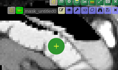 [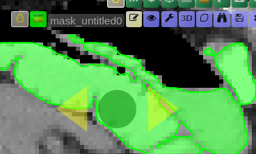move the mouse left/right to adapt size ](https://www.nora-imaging.org/doc/uploads/images/gallery/2020-09/image-1601374884021.png) |
| [](https://www.nora-imaging.org/doc/uploads/images/gallery/2020-09/image-1600428224875.png) | ##### **Polygontool** Use the polygon tool to determine a ROI by its outline. You can either create the outline by holding the mouse button down, or click by click. You can also move points of the outline manually after creation. Use trashcan to delete outline, use the pencil to render the polygon into the current ROI enabled for drawing. [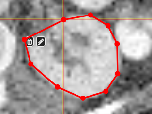](https://www.nora-imaging.org/doc/uploads/images/gallery/2020-09/image-1601375520249.png) [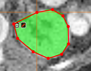](https://www.nora-imaging.org/doc/uploads/images/gallery/2020-09/image-1601375544409.png) |
| [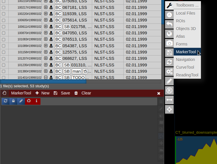](https://www.nora-imaging.org/doc/uploads/images/gallery/2022-03/Marker-Tool-1.png) | [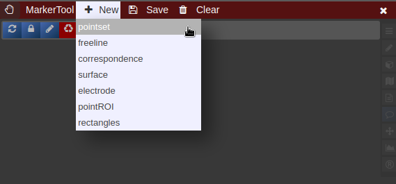](https://www.nora-imaging.org/doc/uploads/images/gallery/2022-03/Marker-Tool-2.png)[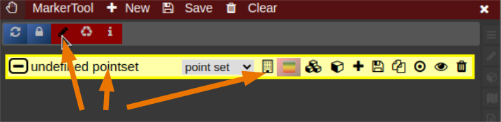](https://www.nora-imaging.org/doc/uploads/images/gallery/2022-03/Marker-Tool-3.png) |
| [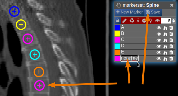](https://www.nora-imaging.org/doc/uploads/images/gallery/2022-03/Marker-Tool-4.png) |